Composite anchor made of glass-fibre reinforced plastic for thermal decoupling of sandwich walls
References
Videos
Do you have any questions?
Documents & Data Sheets
What does this product have to offer?
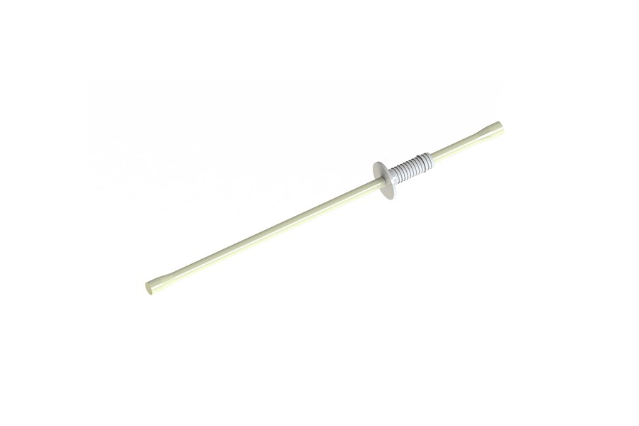
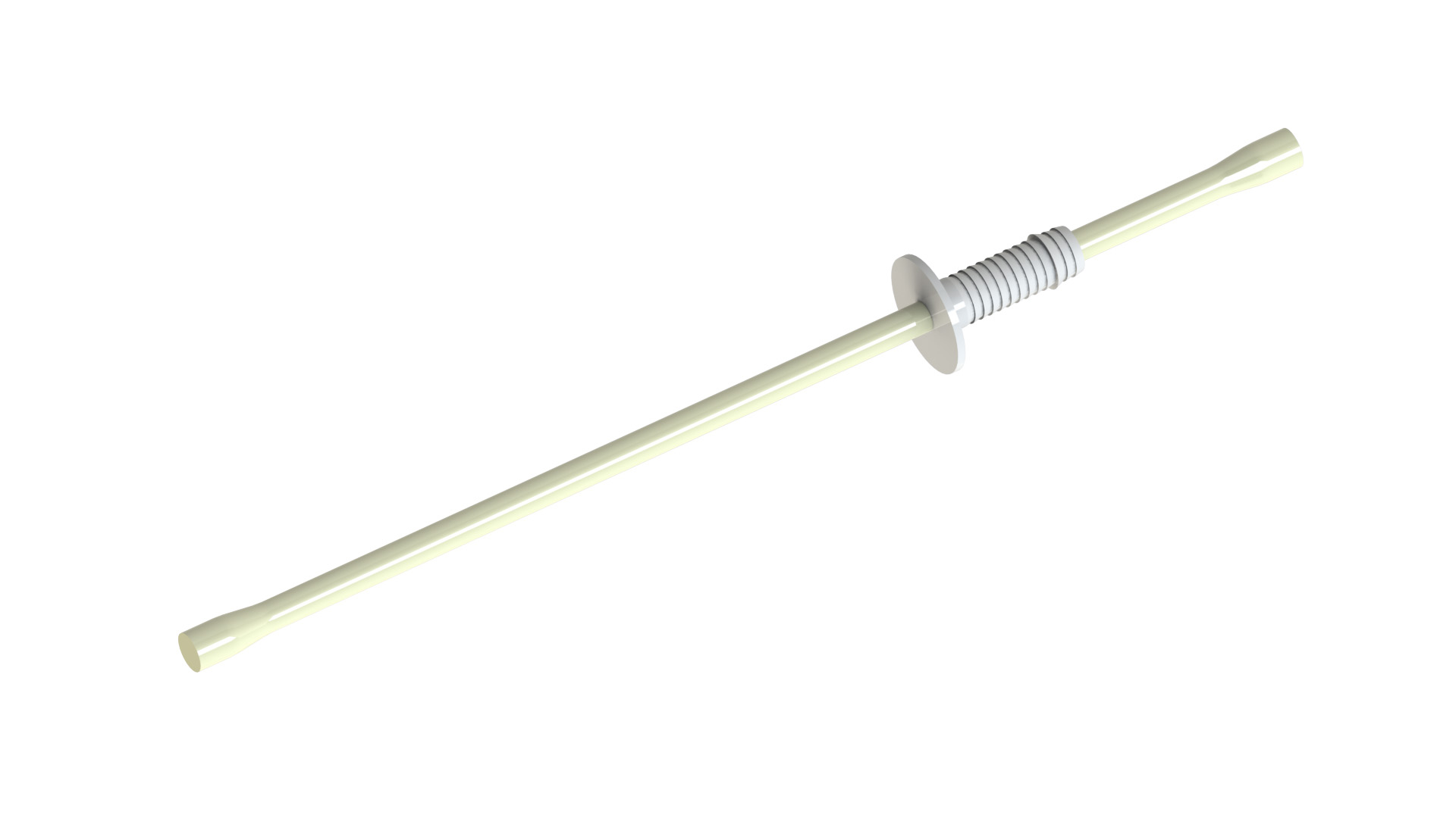
The ThermoPin® is a composite anchor made of glass fibre reinforced plastic (GRP) for sandwich walls and core-insulated double walls.
Your advantages
- Cost-effective - low assembly costs due to quick and easy installation
- durable - tested resistance, even in alkaline media
- slim - constructions with low layer thicknesses possible
Product details
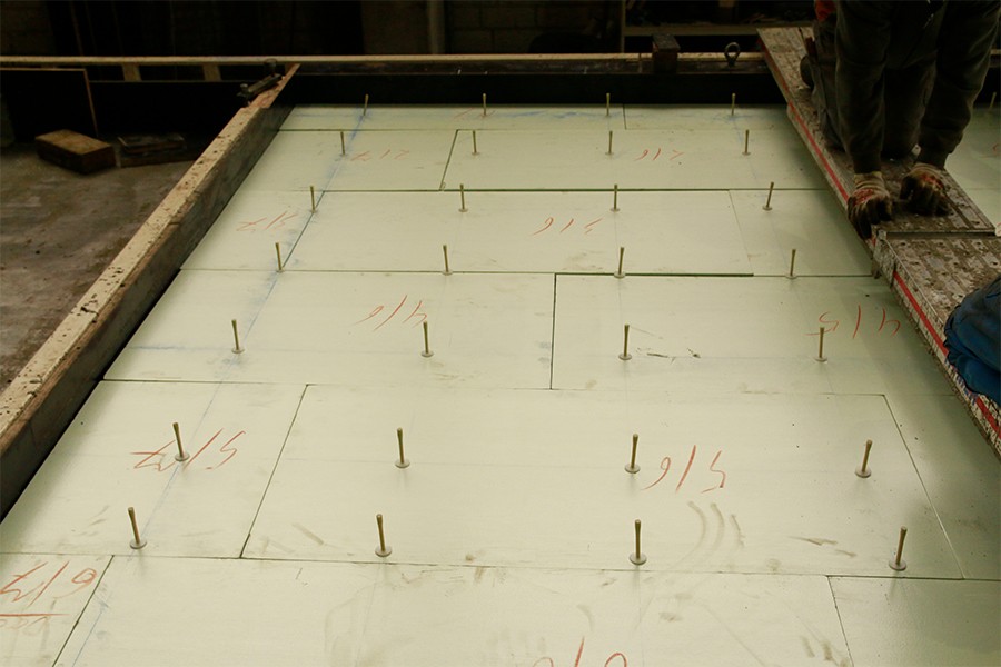
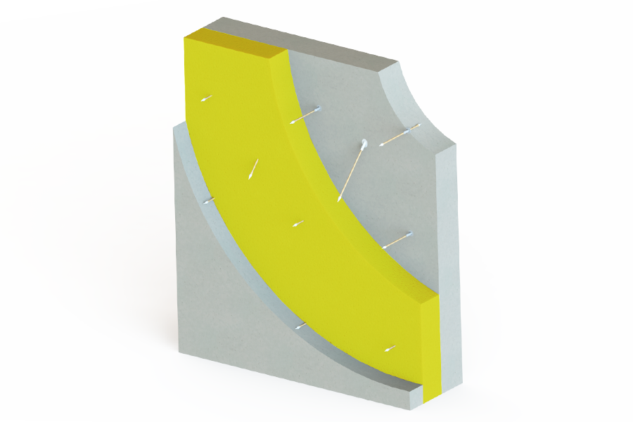
The ThermoPin® is used to connect the facing and load-bearing shell of core-insulated precast concrete elements. The GRP material is suitable for use in slim components.
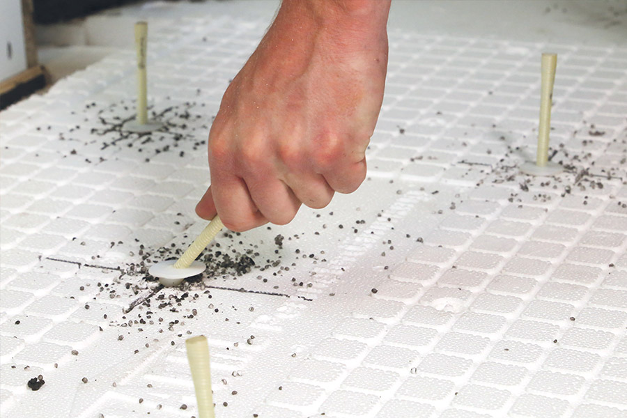
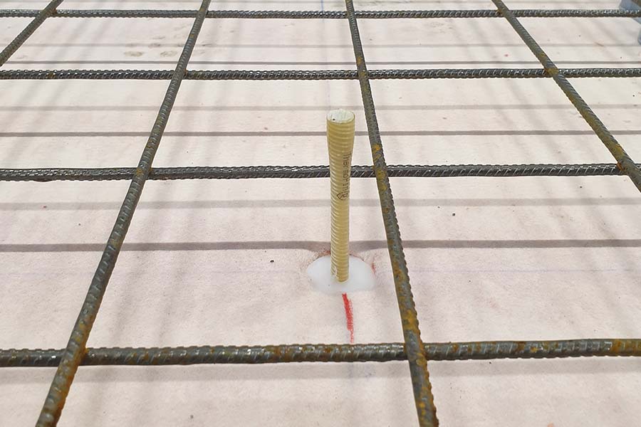
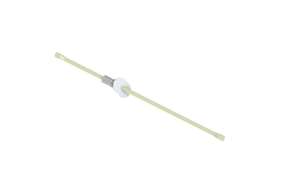
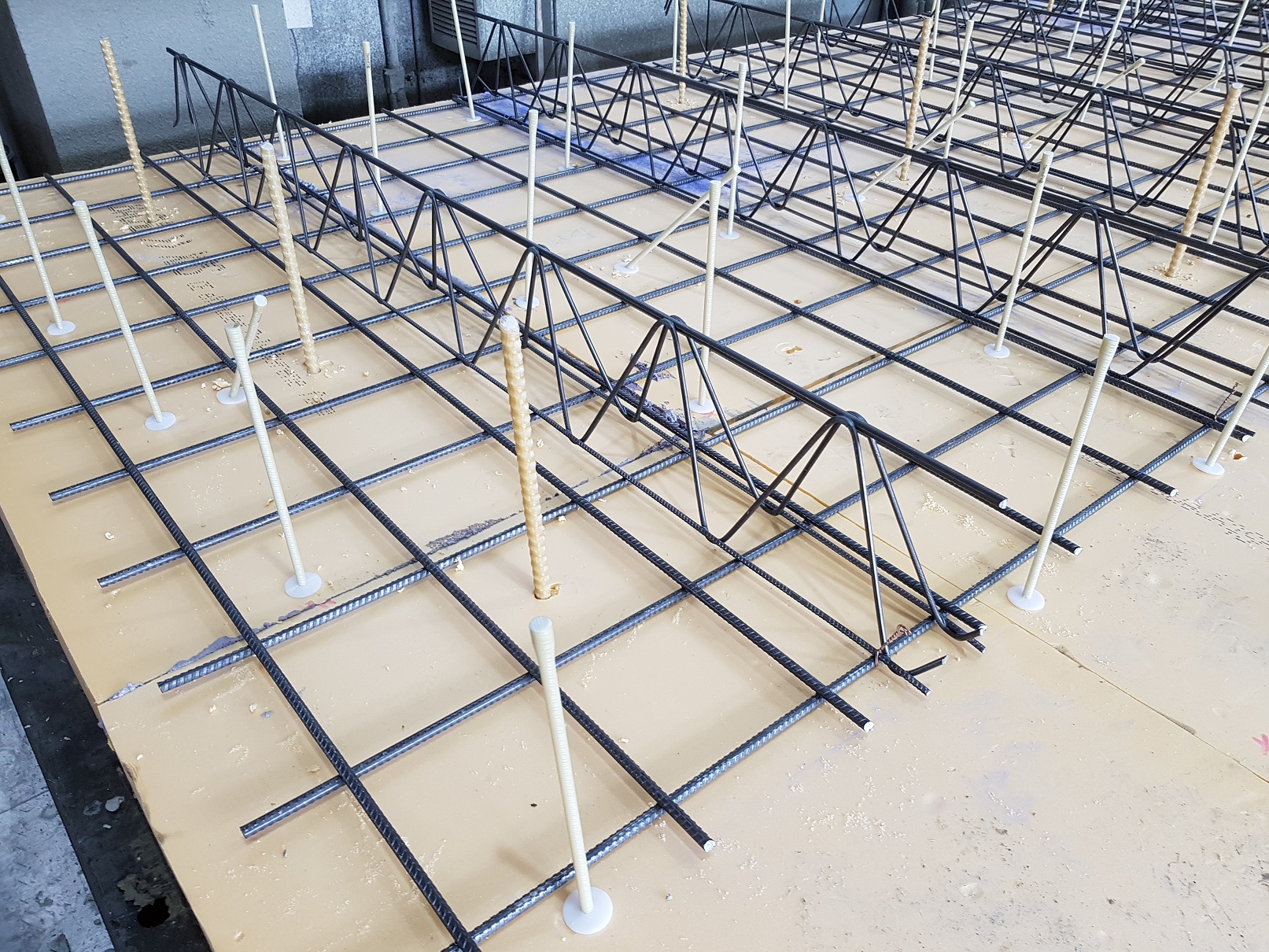
Due to the attached cap, the rod slides easily into the fresh concrete and thus enables a particularly quick installation. The firmly applied sleeve guarantees correct installation and ensures that the penetration point in the insulation is closed and no concrete can flow into the opening. Thus, the bar eventually disappears into the concrete and is not visible on the surface. The result is flawless surfaces without visual deficits.
ThermoPins® are provided with conical widenings at the ends to increase the pull-out resistance. By using only fully intact glass fibres along the rod axis, a particularly high tensile strength is achieved.
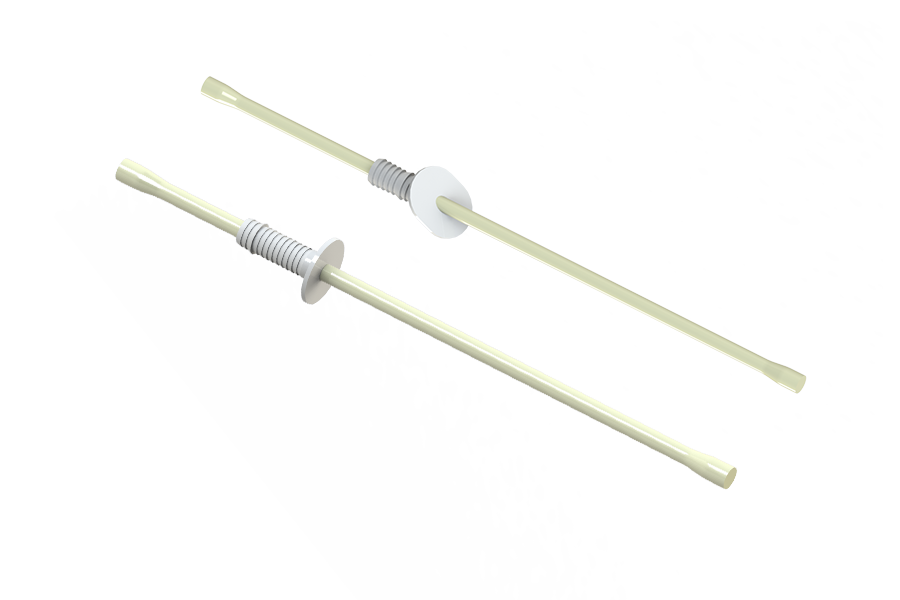
The general technical approval (Z-21.8-2055) and the European Technical Assessment (ETA 19/0498) certify the reliability of the product. The ThermoPin® is available in 2 versions: as a horizontal and diagonal anchor type.
Fields of application of ThermoPin®
- Sandwich walls
- core-insulated double walls
ThermoPin® - Planning software
ThermoPin® planning software is an extension of the BIM/CAD system PLANBAR with a module “Calculation and arrangement of composite anchors (ThermoPin®) for sandwich wall and thermal wall construction systems”. The aim in developing the module of the Allplan Precast CAD system was to develop an additional module in which the selection and placement of ThermoPin® rods type H and type D for individual walls, entire floors or buildings, including drawing, specifications, 3D design and NC data, is automated.
The ThermoPin® is a product approved by the building authorities, which connects facing and load-bearing shells of core-insulated walls without thermal bridges. The number of ThermoPins® to be installed is calculated individually for each wall panel, taking into account the expected forces, and the ThermoPins® are distributed over the surface according to the geometry of the wall panel.
Calculating and drawing in the ThermoPins® can be done manually, but is a very slow and inefficient step. The step of drawing in and scheduling the ThermoPin® is accelerated by our digital solution, which significantly increases the economic efficiency of the ThermoPin®. By integrating it into the PLANBAR software, we give PLANBAR users everything they need to work independently with the ThermoPin®.
Advantages of the ThermoPin® planning software
- Automatic drawing of ThermoPins® in the PLANBAR software from Nemetschek for sandwich walls and thermal walls with and without freely suspended facing layer
- Manually moving ThermoPins®
- Including collision control
- Automatic quantity determination
PLANBAR was chosen as the software environment because of its good market penetration in BT innovation’s core markets. With this step, we are accommodating our customers and accelerating the planning processes.
Precast Software-Engineering is a leading provider of software & services for the precast concrete industry.
The powerful software solutions PLANBAR and TIM together offer an integrated and model-based planning of prefabricated parts with visualization along the entire process. PLANBAR is the comprehensive solution for high-quality, industrialized precast planning. It offers efficient CAD planning and an ideal synthesis of 2D and 3D.
Questions and answers about the product
1. Why does the ThermoPin® have conical extensions at the ends?
The rod is anchored in the concrete by the conical widening of the rod, in the middle the rod is kept slim. As a result, it is flexible and, when deformed, introduces fewer constraints into the component than rigid systems, making the concrete less susceptible to cracking.
2. Why does the ThermoPin® have a cuff?
The ThermoPin® penetrates the insulation and connects the supporting shell with the facing shell. The applied sleeve closes the perforation of the insulation during installation and thus prevents material from flowing into the opening when the concrete is applied to the insulation layer. In addition, the ThermoPin® is tailored to the wall to be manufactured. When properly installed, the collar rests on the top insulation layer and guarantees the correct installation of the ThermoPins®.
3. Why are caps offered with the ThermoPin®?
The caps are used for easy installation of the ThermoPins®. With the help of the caps, the rod slides easily through the insulation and in the concrete. With the help of the cap, the stick can simply slide past obstacles such as small stones.
4. How many bars are used per m²?
The exact calculation of the required number of ThermoPins® to be installed horizontally and diagonally can be carried out according to the DIBt approval, taking into account the load effects and the plate geometries. A blanket statement is not possible. In the case of a sandwich wall, subject to a static calculation, approx. 3 horizontal bars per m² and, in the case of a freely hanging facing shell, an additional diagonal ThermoPin® can be used as a rule of thumb. In the case of a ker-insulated double wall, approx. 6 horizontal bars per m² can be used as a rule of thumb.
5. What does the designation of the ThermoPins® mean?
The ThermoPins® with a horizontal sleeve are called ThermoPin® HL1_L2. The ThermoPins® with a diagonal sleeve are called ThermoPin® DL1_L2. L1 represents the total length of the ThermoPin® in mm and L2 the position of the cuff in mm. The type of cuff is abbreviated H for horizontal and D for diagonal. L2 thus represents the embedment depth of the bar in the second shell, L1 the sum of the insulation thickness and the embedment depth in the first shell. The ThermoPin® H230_80 is a ThermoPin® that can be installed, for example, in a sandwich wall with a facing shell 80 mm thick, an insulating material thickness of 100 mm and a 160 mm thick load-bearing shell. This rod ties 50mm deep into the first shell and 80mm deep into the second shell and bridges 100mm of insulation. The associated ThermoPin® type D is calculated by multiplying the values 230 and 80 by the factor √2. From this follows ThermoPin® D325_110. Your BT contact will be happy to help you select the right ThermoPin® for your project.
